Le nouveau système de télécommande E-Stim sensible au mouvement et à l'audio d'E-Stim Systems offre un contrôle à distance basé sur l'électro dans un petit paquet discret. Simple à utiliser et très efficace.
Si vous recherchez un peu plus dans votre jeu e-stim, alors nous l'avons pour vous avec le nouveau système E-Stim Remote. La télécommande E-Stim originale (maintenant appelée la télécommande classique, était la première unité électroplay au monde à comporter un capteur de mouvement. et maintenant ils sont allés encore plus loin en ajoutant l'audio.
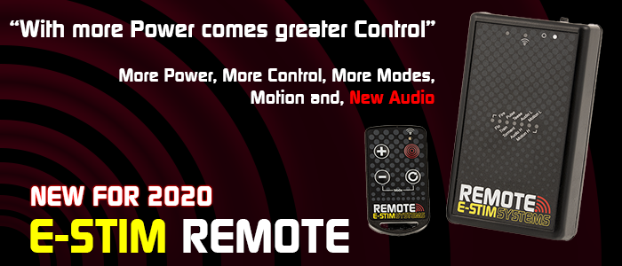
Le nouveau système E-Stim Remote est maintenant l'une des unités E-Stim Remote les plus puissantes au monde, offrant plus de niveaux, plus de contrôle et un nouveau système de forme d'onde de sortie dynamique pour vous fournir tout le contrôle dont vous et votre sujet avez besoin.
Utilisant un nouvel émetteur porte-clés de haute qualité à codage numérique conçu sur mesure et un récepteur discret (offrant une portée allant jusqu'à 100M selon les conditions environnementales), ainsi que plus de modes et de réglages que jamais auparavant, vous pouvez être sûr que le nouveau Remote offre un électroplay télécommandé très efficace et facile à utiliser pour tous.
Caractéristiques clés
Système de radiocommande à codage numérique avec une portée allant jusqu'à 100M
10 modes dont 2 modes de détection de mouvement et 2 nouveaux modes audio
Un émetteur porte-clés à 4 boutons conçu sur mesure et un petit récepteur discret avec clip ceinture
27 niveaux de sortie sur 10 modes différents avec 7 niveaux de réglage dans chaque mode.
La possibilité de relier plusieurs Keyfob et unités d'alimentation.
Safe BiPhasic current limited output with new Dynamic Waveform System
Designed for Play
La nouvelle télécommande E-Stim dispose désormais de 10 modes différents, y compris les nouveaux modes mouvement et audio.
Tout est désormais facilement contrôlable à partir de la simple Keyfob. Elle n'offre pas seulement un simple contrôle du niveau de sortie non plus, Vous pouvez maintenant contrôler les nuances subtiles de la sortie dans chaque mode directement à partir de la Keyfob.
Modes de mouvement
Le capteur de mouvement garantit que le moindre mouvement de votre sujet peut être puni. Si vous vous ennuyez en attendant qu'ils bougent, le bouton Fire peut neutraliser le capteur de mouvement et les faire sauter.
Nouveaux modes audio
La nouvelle télécommande E-Stim dispose désormais de deux nouveaux modes audio. Suffisamment sensibles pour se déclencher sur un claquement de main à plusieurs pieds de distance, les deux nouveaux modes audio ont plusieurs niveaux de sensibilité et deux modes d'affichage vous donnant toutes sortes de nouvelles possibilités intéressantes.
Mode d'entraînement
Le très populaire mode d'entraînement a été étendu, ce qui le rend encore plus facile à utiliser et encore plus efficace.Avec 4 niveaux de puissance... 2505
et 100
ll sur simple pression d'un bouton.
Multiples niveaux de sortie
La sortie est contrôlée numériquement sur 27 niveaux, tous facilement sélectionnables à partir de la télécommande. Chaque étape individuelle est conçue pour augmenter la sortie juste assez pour être efficace, Les nouvelles formes d'ondes dynamiques assurent également que les niveaux plus élevés se sentent encore plus intenses.
Mode d'apprentissage
Chaque Keyfob est codé numériquement à une seule unité de puissance, donc en utilisation normale votre Power Unit ne répondra à aucune autre Keyfob, Cependant la fonction d'apprentissage intégrée permet à plusieurs Power Units de fonctionner en combinaison avec plusieurs Keyfobs, ainsi que l'inverse. En d'autres termes, une télécommande peut contrôler plusieurs unités de puissance, ainsi qu'une unité de puissance répondant à plusieurs télécommandes différentes. Tout cela peut être configuré simplement en quelques secondes.
Plus de puissance
Le générateur de tension de haute qualité contrôlé par microprocesseur signifie que les batteries durent plus longtemps et avec un système d'impulsion généré numériquement, vous pouvez être assuré que la puissance est dirigée exactement là où elle est la plus efficace. Avec le nouveau système de sortie Dynamic, les niveaux plus élevés donnent désormais une puissance considérablement plus importante.
Clip ceinture
L'unité de réception est équipée d'un clip ceinture, facile à glisser dans une sangle, une ceinture, une poche ou tout ce à quoi vous pouvez penser. Le clip de ceinture est également fermement fixé à l'unité d'alimentation - il est donc peu probable que vous le perdiez.
Compatibilité
Le système de télécommande E-Stim dispose d'une prise de sortie robuste de 3,5 mm et est compatible et suffisamment puissant pour fonctionner avec toutes les électrodes des systèmes E-Stim.
Sécurité, qualité et avec une garantie à vie
Le système de télécommande E-Stim est conçu et fabriqué au Royaume-Uni pour se conformer aux dernières normes de sécurité britanniques et européennes, et contrairement à certaines unités e-stim importées, le système de télécommande n'est pas seulement livré avec un marquage CE, il est livré avec une garantie à vie complète E-Stim Systems.
Spécifications techniques
Canaux/sorties : : Radiocommandé monocanal, via une prise mono 3,5 mm
Affichage : : LED haute luminosité indiquant la mise sous tension, la sortie et l'activité du récepteur ainsi que la nouvelle barre d'état
Modes de fonctionnement : : 10, Feu, Continu, Impulsion, Mouvement et Entraînement avec 27 niveaux de sortie et 7 niveaux de réglage dans chaque mode.
Contrôles : : Unité d'alimentation : mise sous tension/hors tension, apprentissage Sélection de la télécommande : haut, bas, réglage et tir
Forme d'onde de sortie : : CA pulsé à courant limité biphasique avec des formes d'onde dynamiques
Spécification radio : : Keyloc encodé numériquement 433Mhz
Alimentation électrique : : Unité d'alimentation : Standard 9 Volt Alkaline (PP3), Keyfob : Pile CR2032 (fournie)
Dimensions (approximatives.) : : Unité d'alimentation : 112mm x 65mm x 41mm, Porte-clés : 33mm x 59mm x 8mm
Glückwunsch zum Kauf eines neuen E-Stim Remote Systems. Bei ausreichender Pflege sollte Ihnen Ihr Remote System viele Jahre lang erotisches, elektrostimuliertes Vergnügen bereiten. Bevor Sie beginnen, lesen Sie bitte die Gebrauchsanweisung und machen Sie sich mit allen Bedienelementen und den Sicherheitshinweisen vertraut.
10 einstellbare Steuermodi mit 27 Leistungsstufen, die alle über einen eigenen digitalen 4-Tasten-Keyfob gesteuert werden können.
Eingebautes Dual Mode Audio getriebenes Triggersystem mit einstellbarer Empfindlichkeit und Reaktion.
Einstellbarer Bewegungssensor
Einzigartig digital kodierte Schlüsselanhänger-Sender. Die Geräte reagieren nicht auf andere Funkquellen.
Bis zu 100M Reichweite
Im LEARN Modus können mehrere Schlüsselanhänger in Kombination mit mehreren Power Units verwendet werden.
Neuer Dynamic Drive Einkanalausgang ermöglicht die Verwendung von unipolaren und bipolaren Elektroden.
Strombegrenzter AC-Ausgang, um die Sicherheit zu gewährleisten und die Möglichkeit einer Elektrodenpolarisierung zu vermeiden.
SICHERHEITSWARNUNG
VERBINDEN SIE DAS E-STIM REMOVE SYSTEM ODER JEGLICHE ELEKTRISCHEN GERÄTE NICHT AN IRGENDEINE STELLE ÜBER DER HÜFTE AN (ÜBER DEN ARMEN ZÄHLT ALS ÜBER DER HÜFTE!), ABER BESONDERS NICHT ÜBER DEM HERZEN, DER BRUST, DEM HALS ODER DEM KOPF AN. NICHT VERWENDEN, WENN SIE EINEN HERZSCHRITTMACHER TRAGEN ODER SCHWANGER SIND. DENKEN SIE DARAN, DASS SIE DIESES GERÄT AUF EIGENE GEFAHR BENUTZEN. SIE MÜSSEN DIE GEBRAUCHSANWEISUNG UND ALLE ANDEREN ANWEISUNGEN LESEN UND VERSTEHEN, BEVOR SIE DAS GERÄT IN BETRIEB NEHMEN.
Was ist enthalten?
Inhalt
Das neue E-Stim Remote System besteht aus zwei Einheiten, einem kleinen Handsender im Stil eines Schlüsselanhängers und dem Funkempfänger, die Power Unit. Die Power Unit wird an eine Elektrode angeschlossen, die an der Person angebracht oder in sie eingeführt wird, während der Schlüsselanhänger-Sender die Steuerung aus einer Entfernung von bis zu 50 m ermöglicht. Das Paket enthält außerdem einen Satz Klebepads, ein 2-mm-TENS-Verbindungskabel und eine Batterie für die Power Unit (die Batterie für den Schlüsselanhänger (CR2032) ist bereits eingebaut). Außerdem wird eine Kurzanleitung mitgeliefert, die Ihnen einen schnellen Einblick in die Bedienelemente gibt, wenn Sie keinen Zugang zu dieser Online-Anleitung haben.
Die Entfernung, über die die Power Unit auf den Sender des Schlüsselanhängers reagiert, hängt stark von der Umgebung, dem Batteriestand und einer Reihe anderer Faktoren ab.
Die Fernbedienung ermöglicht 27 Leistungsstufen in 10 verschiedenen Modi. Alle Steuerungen, einschließlich der Auswahl von Pegel und Modus, erfolgen über ein einfaches Auf-/Ab-/Auswahlsystem auf dem Schlüsselanhänger.
Das System erlaubt auch die Verwendung mehrerer Schlüsselanhänger und Empfänger. Da jeder Schlüsselanhänger einen einzigartigen Code generiert, ist es möglich, einem Gerät beizubringen, auf mehrere Schlüsselanhänger zu reagieren, und umgekehrt ist es auch möglich, mehrere Empfänger zu haben, die auf einen einzigen Schlüsselanhänger reagieren.
Vor der Benutzung
Bevor Sie Ihre E-Stim Systems Power Unit verwenden können, müssen Sie sicherstellen, dass die Power Unit den Schlüsselanhänger erkannt hat und auf ihn reagiert. Wenn Sie eine Batterie in den Empfänger einlegen, das Gerät ohne angeschlossene Elektroden einschalten und die rote Taste am Schlüsselanhänger drücken, sollten zwei LEDs am Empfänger aufleuchten. Die RX-LED sollte flackern und die Output-LED sollte so lange leuchten, wie die rote Taste auf dem Schlüsselanhänger gedrückt wird.
Wenn die Aktivitäts-LED flackert, aber die Output-LED nicht leuchtet, bedeutet dies, dass die Power Unit den Schlüsselanhänger nicht erkannt hat. In diesem Fall müssen Sie die LEARN Prozedur durchführen.
Einschalten
Beim Einschalten führt die Power Unit einen Selbsttest durch und zeigt den Batteriestand an, bevor es den zuletzt verwendeten Modus auswählt. Das Remote System merkt sich den Modus, in dem sich das Gerät beim letzten Ausschalten befand, sowie die eingestellten Werte. Um das Gerät auf die Werkseinstellungen zurückzusetzen, befolgen Sie das Verfahren zum Zurücksetzen auf die Werkseinstellungen. Der Ausgangspegel wird immer auf Null gesetzt, wenn das Gerät eingeschaltet wird.
Benutzung des Remote Systems
Schritt 1 Batterien einlegen Der Schlüsselanhänger wird mit eingelegter Batterie geliefert.
Schritt 2 Vergewissern Sie sich, dass der Schlüsselanhänger mit dem Steuergerät verbunden ist (LEARN Modus)
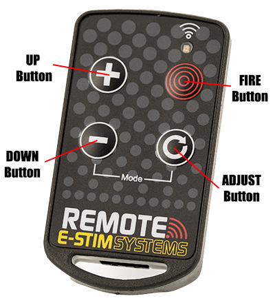
Machen Sie sich mit den Bedienelementen des Schlüsselanhängers vertraut.
Abhängig vom Modus erhöht die Taste UP im Allgemeinen den Ausgangspegel, die Taste DOWN verringert den Ausgangspegel und die Taste FIRE aktiviert oder übersteuert den Ausgang, je nach dem aktuell gewählten Modus. Die ADJUST-Taste ermöglicht, in jedem Modus die Einstellungen anzupassen. Im Trainingsmodus gibt die Down-Taste 25 % Leistung, die ADJUST-Taste 50 % Leistung, die UP-Taste 75 % Leistung und die FIRE-Taste 100 % Leistung.
Durch gleichzeitiges Drücken der Tasten DOWN und ADJUST wird die Modussteuerung aktiviert, mit der die jeweiligen Modi ausgewählt werden. Siehe Modussteuerung.
Das Gedrückthalten der UP- oder DOWN-Taste erhöht oder verringert die Leistung in größeren Schritten. Wenn Sie eine Taste länger als etwa 30 Sekunden gedrückt halten, schaltet sich der Schlüsselanhänger automatisch ab, um die Batterien zu schonen (dies soll verhindern, dass der Schlüsselanhänger versehentlich in einer Tasche aktiviert wird). Sollte dies der Fall sein, lassen Sie die Taste einfach los und drücken Sie erneut.
Wenn die LED auf dem Schlüsselanhänger schwach leuchtet und die Reichweite verringert ist, muss die Batterie des Schlüsselanhängers möglicherweise ausgetauscht werden.
Anschließen einer Elektrode
Vergewissern Sie sich, dass das Netzteil ausgeschaltet ist, und schließen Sie eine geeignete Elektrode über die Ausgangsbuchse an. Schließen Sie dann eine Elektrode an einer geeigneten Stelle des Körpers an. (SCHLIESSEN SIE DIE Power Unit ODER JEGLICHE ELEKTRISCHE GERÄTE NICHT AN EINER STELLE ÜBER DER TAILLE AN (ÜBER DEN ARMEN ZÄHLT ALS ÜBER DER TAILLE!), ABER VOR ALLEM NICHT ÜBER DAS HERZ, DIE BRUST, DEN HALS ODER DEN KOPF. NICHT VERWENDEN, WENN SIE EINEN HERZSCHRITTMACHER TRAGEN ODER SCHWANGER SIND. VERGESSEN SIE NICHT, DASS SIE DIESES GERÄT AUF IHR EIGENES RISIKO VERWENDEN.
Schalten Sie das Gerät ein, die Output-LED sollte 4 Mal blinken und automatisch den vorherigen Modus 1 wählen, dann drücken Sie die rote Taste. Ihre Testperson spürt möglicherweise ein leichtes Kribbeln an der Elektrodenstelle. Wenn nicht, erhöhen Sie den Pegel und versuchen Sie es erneut. Passen Sie den Ausgangspegel nach Bedarf an.
Wenn Sie oder Ihre Testperson Schmerzen oder Unbehagen verspüren, beenden Sie die Anwendung sofort. Wir empfehlen die Verwendung eines leitfähigen Gleitmittels, da jedes E-Stim-Gerät bei hohen Leistungsstufen an empfindlichen oder kleinen Kontaktstellen zu Verbrennungen führen kann.
Stets sicherstellen, dass alle Anschlüsse sicher und frei von Korrosion sind.
Den Ausgang NICHT KURZSCHLIESSEN. Versuchen Sie NICHT, die Power Unit zu öffnen. Auch bei ausgeschaltetem Gerät liegen Hochspannungen an, und es befinden sich keine vom Benutzer zu wartenden Teile im Inneren. Das Öffnen des Netzteils führt zum Erlöschen der Garantie.
Batterien einlegen
Sowohl der Schlüsselanhänger als auch die Power Unit benötigen zum Betrieb Batterien. Der Schlüsselanhänger wird mit einer Batterie geliefert, während in die Power Unit eine Batterie eingesetzt werden muss (nicht im Lieferumfang enthalten).
Einlegen einer Batterie (Power Unit)
Versichern Sie sich, dass das Gerät ausgeschaltet ist und alle Elektrodenanschlusskabel abgezogen sind.
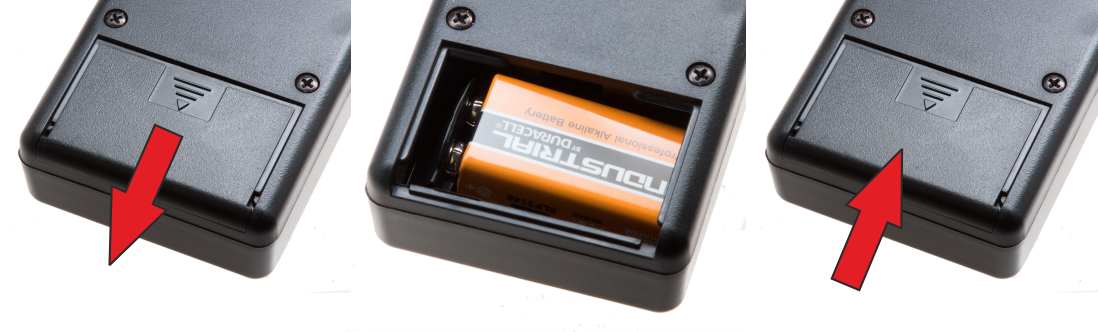
Das Gerät umdrehen, leicht auf die Mitte der Batterieabdeckung drücken und die Abdeckung nach unten schieben.
Entfernen Sie die alte Batterie (falls vorhanden) und ersetzen Sie sie durch eine neue Alkalibatterie PP3. Der Batteriestecker ist polarisiert, so dass es nicht möglich sein sollte, die Batterie falsch anzuschließen, aber stellen Sie sicher, dass die Polarität richtig ist, bevor Sie den Anschluss versuchen.
Legen Sie die Batterie in das Gerät ein und schließen Sie das Batteriefach. Der Deckel lässt sich verschieben und sollte dann einrasten.
Drehen Sie das Gerät um. Das Gerät ist nun betriebsbereit.
Bitte beachten Sie, dass wir die Verwendung von Zink-Kohle-Batterien oder wiederaufladbaren Standardbatterien in der E-Stim Systems Remote Power Unit NICHT empfehlen. Wiederaufladbare NiMh-Batterien mit einer Klemmenspannung von 8,4 V oder mehr können verwendet werden, wobei sich die Ausgangsleistung verringern kann.
Wenn die Power Unit eine Zeit lang nicht benutzt wird, entfernen Sie die Batterie, um mögliche Schäden durch Auslaufen der Batterie zu vermeiden.
Einlegen einer Batterie (Schlüsselanhänger)
Stellen Sie vor dem Batteriewechsel sicher, dass die Power Unit ausgeschaltet und von allen Elektroden getrennt ist. Der Schlüsselanhänger wird mit einer eingebauten Batterie (CR2032) geliefert.
Um die Batterie auszutauschen, verwenden Sie einen kleinen Kreuzschlitzschraubendreher, um die beiden Schrauben auf der Rückseite des Schlüsselbundes zu lösen, wobei Sie darauf achten müssen, diese nicht zu verlieren.
Öffnen Sie das Gehäuse und nehmen Sie die Batterie vorsichtig heraus. Legen Sie die neue Batterie ein, achten Sie dabei auf die Polarität, die durch ein '+' auf der Platine und der Batterie gekennzeichnet ist, und schließen Sie das Gehäuse.
Setzen Sie die Schrauben wieder ein und schrauben Sie den Schlüsselanhänger wieder zusammen.
Überprüfen Sie, ob die Batterie richtig eingelegt wurde, indem Sie eine Taste am Schlüsselanhänger drücken (stellen Sie sicher, dass alle Netzteile in Reichweite ausgeschaltet sind). Die gelbe LED auf dem Schlüsselanhänger sollte für die Dauer des Tastendrucks blinken. Sollte dies nicht der Fall sein, überprüfen Sie, ob Sie die Batterie richtig eingesetzt haben.
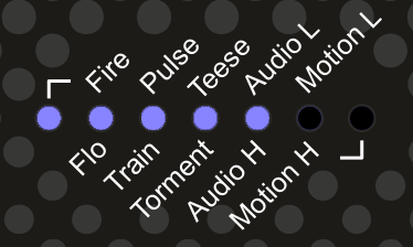
Pegelsteuerung
Die meisten Modi verwenden die UP- und DOWN-Tasten, um den Pegel zu steuern. Wenn die Stufe ausgewählt ist, wird die Stufe in der Statusleiste angezeigt, es sei denn, Sie befinden sich im diskreten Modus. Da wir 28 Stufen anzeigen müssen (wir zählen Null nicht als Stufe, aber es ist eine), müssen wir 4 verschiedene Stufen zwischen jeder LED anzeigen. Mit zunehmender Stufe zeigt die Statusanzeige ein wachsendes Balkendiagramm an, bei dem jede einzelne LED langsam blinkt, schneller blinkt, noch schneller blinkt und dann in ein dauerhaftes Leuchten übergeht. Dann setzt die nächste LED in der Anzeige den Zyklus fort. Ein Beispiel:
langsames Blinken
Stufe 1
mittleres Blinken
Stufe 2
schnelles Blinken
Stufe 3
dauerhaftes Leuchten
Stufe 4
Das Drücken und Halten der UP oder DOWN Taste führt dazu, dass das Level zur nächsten 4. Stufe springt, also 4 8 12 16 20 usw. usw. Wenn Sie die DOWN Taste kontinuierlich gedrückt halten, wird schließlich die Nullstufe erreicht, und ein kurzer LED-Wisch wird angezeigt.
Im diskreten Modus wird die Füllstandsanzeige nicht angezeigt.
Einstellungsmöglichkeiten
Die meisten Modi verfügen über Einstellungsmöglichkeiten. Durch wiederholtes Drücken und Loslassen der Taste ADJUST werden die einzelnen Einstellungen für den aktuellen Modus durchlaufen, wobei die Wirkung der tatsächlichen Einstellung vom Modus abhängt. Nach dem Loslassen der ADJUST-Taste leuchtet die Punktanzeige für einige Sekunden.
Wenn der diskrete Modus gewählt wurde, wird die Anzeige der Einstellpunkte nicht angezeigt.
Modussteuerung
Modusauswahl
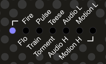
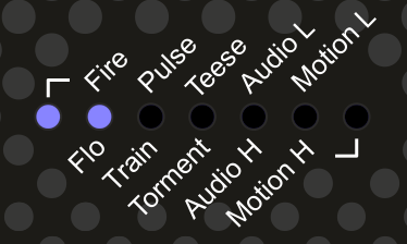
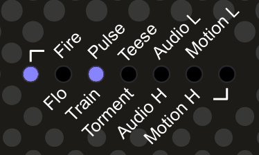
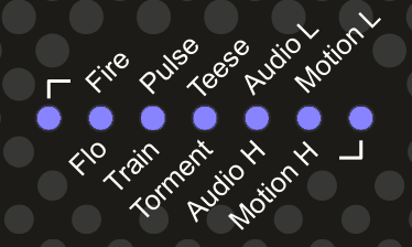
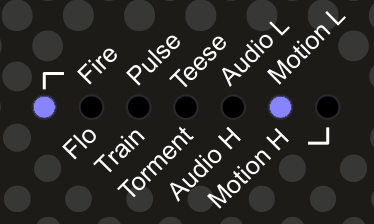
Durch gleichzeitiges Drücken der Tasten DOWN und ADJUST auf dem Schlüsselanhänger GLEICHZEITIG wird das Gerät in den Modusauswahlmodus geschaltet, was durch zwei durchgehende LEDs auf der Statusleiste des Empfängers angezeigt wird. Die Position der LEDs zeigt den aktuellen Modus an, die linke ganz links zeigt an, dass die Modi in der oberen Reihe ausgewählt werden können, die LED ganz rechts zeigt an, dass die Modi in der unteren Reihe ausgewählt werden können. Ein Modus ist erst dann ausgewählt, wenn die ADJUST Taste gedrückt wurde.
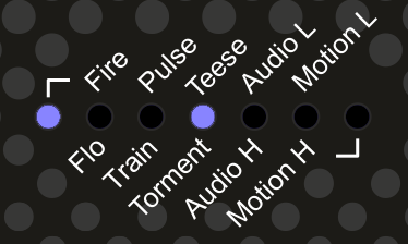
Durch Drücken der Tasten UP oder <DOWN werden die Modi nach oben und unten durchlaufen. Durch Drücken der Taste ADJUST wird der aktuell ausgewählte Modus aktiviert. Der Modus ist erst dann aktiv, wenn er ausgewählt wurde. Der Modus wird durch die linke oder rechte LED angezeigt, die angibt, ob Sie sich am Anfang oder am Ende der Liste der Modi befinden, und dann durch eine zweite LED, die den Modus anzeigt. Dies ist zum Beispiel der Modus FIRE.
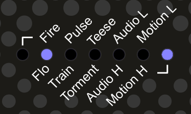
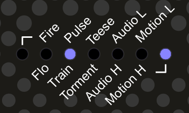
Und das ist der Flo-Modus
Wenn der Modus ausgewählt wurde, blinkt die Statusanzeige dreimal und dann wird der Ausgangspegel automatisch auf Null und der Einstellwert auf 1 gesetzt. Der aktuelle Modus wird beim Ausschalten des Netzteils gespeichert.
Die Modi sind wie folgt.
Fire-Modus
Der klassische Fernbedienungsmodus. Die Tasten UP und DOWN steuern den Ausgangspegel (Null bis 27), während das Drücken der Taste FIRE den Ausgang mit dem gewählten Pegel aktiviert und den Ausgangspegel auf dem Statusdisplay anzeigt (es sei denn, Sie befinden sich im diskreten Modus). Der Ausgang ist so lange aktiv, wie die Fire-Taste gedrückt wird. Nach etwa 25-30 Sekunden schaltet der Schlüsselanhänger den Ausgang ab. Die Ausgangs-LED leuchtet nur, wenn der Ausgang aktiv ist. Mit der Adjust-Taste kann das Gefühl des Ausgangs über 7 verschiedene Werte verändert werden.
Flo-Modus
Ein kontinuierlicher Ausgabemodus. Die Tasten UP und DOWN regeln den Ausgangspegel (Null bis 27), während das Drücken der Taste FIRE einen um 4 Stufen höheren Ausgangspegel als die aktuelle Einstellung bewirkt (vorausgesetzt, es sind noch Stufen vorhanden und der Pegel ist nicht auf Null eingestellt. Wenn die Power Unit auf Stufe Null eingestellt ist, wird der Ausgang nicht im Boost-Modus arbeiten, wenn die Fire-Taste gedrückt wird. ) Adjust durchläuft mehrere verschiedene "Gefühle". Helix. Im Betrieb leuchtet die Ausgangs-LED kontinuierlich. Der Level-Ausgang wird im diskreten Modus nicht angezeigt.
Pulse-Modus
Ein gepulster Ausgangsmodus. Die Tasten UP und DOWN steuern den Ausgangspegel (Null bis 27), während die Taste ADJUST durch 7 verschiedene Impulsgeschwindigkeiten von langsam bis schnell schaltet. Die Taste FIRE übersteuert den Ausgang, um einen kontinuierlichen Ausgang zu erzeugen. Im diskreten Modus wird der Ausgangspegel nicht angezeigt.
Trainingsmodus
Der klassische ""Trainingsmodus"" Sie müssen sich keine Gedanken darüber machen, welchen Pegel der Ausgang hat, wenn Sie den ersten Knopf drücken, da die Ausgänge vorgewählt sind. DOWN Button gibt 25% Output, ADJUST 50% UP 75% und FIRE 100%. Vorausgesetzt, Sie verwenden nicht den diskreten Modus, zeigt die Statusanzeige den Ausgangspegel an.
25%
50%
75%
100%
Teese
Ein kontinuierlicher Ausgabemodus mit einem ansteigenden Gefühl, das durch eine sich bewegende LED in der Statusleiste angezeigt wird. Sobald ein Zyklus abgeschlossen ist, beginnt er wieder bei Null. Die UP und DOWN Tasten regeln den Pegel, und die FIRE-Taste erhöht den Ausgang um 4 Stufen über den aktuellen Ausgang. Die Anhebung funktioniert nicht, wenn der Ausgangspegel auf Null gesetzt ist. Die Taste ADJUST steuert die Geschwindigkeit des Zyklus, wobei 7 verschiedene Geschwindigkeiten zur Verfügung stehen.
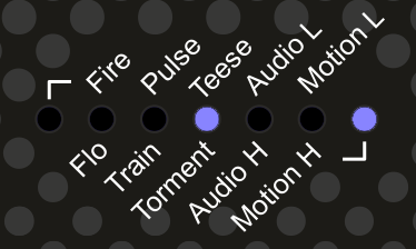
Torment
Ein kontinuierlicher Ausgabemodus mit einem ansteigenden und abfallenden Gefühl, das durch eine sich bewegende LED in der Statusleiste angezeigt wird. Sobald ein Zyklus abgeschlossen ist, kehrt sich der Zyklus um. Die UP und DOWN Tasten steuern den Pegel, und die FIRE-Taste erhöht den Output um 4 Stufen über den aktuellen Output. Die Anhebung funktioniert nicht, wenn der Ausgangspegel auf Null gesetzt ist. Die Taste ADJUST steuert die Geschwindigkeit des Zyklus, wobei 7 verschiedene Geschwindigkeiten zur Verfügung stehen.
Audiomodi
Audiomodi verwenden Ton, um den Ausgang zu aktivieren. Die Art des Klangs, die Entfernung der Klangquelle vom Gerät, der Pegel und die Einstellungen des Geräts in Bezug auf den Modus und die gewählte Einstellung wirken sich alle darauf aus, wie der Klang als E-Stim-Empfinden empfunden wird.
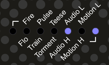
Audio Low Modus
Verwendet das eingebaute Mikrofon, um die Ausgabe auszulösen. Die Taste ADJUST steuert die Reaktion, von hochsensibel bis weniger sensibel. Die Pegelregler UP und DOWN stellen ein Vielfaches des Eingangs zur Verfügung, so dass ein maximaler Eingang mit dem Pegel 27 (voll) den maximalen Ausgang ergibt, während der gleiche Eingang mit dem Pegel 14 die Hälfte des Ausgangs ergibt. Die Taste FIRE übersteuert künstlich das Eingangssignal, was 100% Input entspricht. Der Audio-Low-Modus ist nicht so empfindlich wie der Audio-High-Modus und eignet sich besser für den Einsatz in lauteren Umgebungen.
Audio High Modus
Benutzt das eingebaute Mikrofon zum Auslösen des Ausgangs mit einer höheren Empfindlichkeit als der Audio Low Modus. UP und DOWN regeln den Pegel des Ausgangssignals, ADJUST regelt die Empfindlichkeit und FIRE überschreibt das Ausgangssignal. 7 Stufen können über die ADJUST Taste eingestellt werden. Die Anzeige unterscheidet sich vom Audio-Low-Modus, da es sich um eine Balkenanzeige handelt, die von der linken Seite aus ansteigt und somit eine empfindlichere Anzeige bietet. Die Taste FIRE übersteuert künstlich die Eingabe, was einem 100%igen Eingangssignal entspricht.
Motion Low Mode
Bewegungsempfindlicher Modus. Die Tasten UP und DOWN steuern den Ausgangspegel (1-27), während das Drücken der Taste FIRE den Bewegungsauslöser außer Kraft setzt und den Ausgang aktiviert. Wenn die Power Unit zu stark bewegt wird, wird der Ausgang ausgelöst. ACHTUNG! Er ist sehr empfindlich! Im Betrieb flackert die Ausgangs-LED, wenn der Ausgang aktiv ist.
Der Bewegungssensor ist sehr empfindlich. Im Betrieb zählt der interne Mikroprozessor, wie oft der Sensor ausgelöst wird, und wenn dieser einen bestimmten Wert erreicht, wird der Ausgang ausgelöst. Mit zunehmendem Pegel steigt die Balkenanzeige an. Sobald alle 7 Balken aufleuchten, wird der Ausgang ausgelöst. Der Auslösepunkt ist je nach Einstellung variabel. Sollte keine Bewegung erfolgen, wird die Balkenanzeige mit der Zeit abnehmen. Durch Drücken der Taste FIRE wird der Ausgang übersteuert und das Objekt "gezappt", was möglicherweise zu noch mehr Bewegung führt!!!
Der Bewegungssensor ist in jeder Ausrichtung aktiv.
Power Unit (Empfänger)
Die Power Unit hat zwei einfache Bedienelemente und 3 Displays.
Anzeigen der Power Unit
LED
Verwendung
Ausgabe (Output)
Zeigt die Ausgangsaktivität und den Modus an. Im Moduswahlmodus zeigt die Anzahl der Blinksignale den Modus an. Beim Einschalten blinkt die Ausgangs-LED 3 Mal in schneller Folge.
Statusleiste
Zur Anzeige des Batteriestands, des aktuellen Ausgangspegels, des Modus und der Einstellung
RX
Zeigt die Funkaktivität an. Zeigt auch an, wenn sich das Bedienteil im LEARN-Modus befindet. Beachten Sie, dass die RX-LED Aktivität anzeigt, wenn ein kompatibler Schlüsselanhänger innerhalb der Reichweite verwendet wird, auch wenn dieser Schlüsselanhänger nicht vom Empfänger eingelernt wurde.
Bedienelemente der Power Unit
Steuertaste
Verwendung
oberer Schiebeschalter
Schaltet das Gerät ein und aus.
LEARN-Taste (im Batteriefach)
Wird während des LEARN-Vorgangs verwendet.
Ausgänge des Netzteils
Ausgang
Verwendung
3,5mm Mono-Buchse
Spannungsausgang zur Elektrode.
Learn Modus
Was ist das?
Im Lernmodus kann der Benutzer auswählen, auf welche Schlüsselanhänger die Power Unit reagieren soll. Es ist möglich, einer Power Unit beizubringen, auf bis zu 50 verschiedene Schlüsselanhänger zu reagieren, und es ist auch möglich, mehr als einer Power Unit beizubringen, auf denselben Schlüsselanhänger zu reagieren.
Die Power Unit wird anfänglich mit einem Schlüsselanhänger geliefert, der während der Testphase mit der Power Unit verbunden ist und "out of the box" funktionieren sollte. Der Lernmodus wird in der Regel nur benötigt, wenn Sie Ersatz- oder zusätzliche Schlüsselanhänger oder Empfänger erworben haben
Die Lerntaste befindet sich im Inneren des Batteriefachs. Öffnen Sie das Batteriefach, nehmen Sie die Batterie heraus, aber trennen Sie sie nicht, und Sie sollten die Lerntaste darin finden. Die Lerntaste funktioniert nur, wenn die Power Unit mit einer Batterie verbunden und eingeschaltet ist, also NICHT DIE BATTERIE ABNEHMEN.
Löschen des Speichers der Power Unit
Löschen aller Schlüsselanhänger. Dadurch werden alle Schlüsselanhänger aus dem Speicher der Power Unit gelöscht.
Entnehmen Sie die Batterie aus dem Batteriefach, stellen Sie aber sicher, dass sie noch angeschlossen ist. Schalten Sie die Power Unit ein. Halten Sie die Lerntaste für mindestens 10 Sekunden gedrückt. Die RX-LED leuchtet auf. Lassen Sie die Lerntaste los. Die RX-LED sollte nun etwa 10 Mal blinken und dann aufhören. Der Speicher ist nun gelöscht.
Einlernen einer Fernbedienung durch die Power Unit.
Entnehmen Sie die Batterie aus dem Batteriefach, stellen Sie aber sicher, dass sie noch angeschlossen ist. Schalten Sie die Power Unit ein.
Drücken Sie die Lerntaste einmal. Die RX-LED sollte aufleuchten. Drücken Sie eine Taste auf dem Schlüsselanhänger, den Sie mit dem Empfänger verwenden möchten. Die RX-LED sollte nun erlöschen. Drücken Sie die Taste erneut. Die RX-LED sollte nun einige Male blinken. Die Power Unit hat nun den Schlüsselanhänger "erlernt" und wird auf den Schlüsselanhänger reagieren. Es können auch weitere Schlüsselanhänger hinzugefügt werden, so dass eine Power Unit auf mehr als einen Handsender reagieren kann. Es ist auch möglich, einen einzelnen Schlüsselanhänger zu mehr als einer Power Unit hinzuzufügen, was noch mehr Möglichkeiten bietet.
Ausgänge
Der Anschluss an die Elektroden erfolgt über eine einzelne 3,5-mm-Mono-Klinkenbuchse auf der Oberseite des Empfängers. Vergewissern Sie sich, dass das Gerät ausgeschaltet ist, bevor Sie die Anschlussbuchsen einstecken oder entfernen, um die Möglichkeit eines versehentlichen Stromschlags oder Kurzschlusses auszuschließen. Wir empfehlen die Verwendung von 3,5-mm-Winkelsteckern von E-Stim Systems, da dies die Möglichkeit einer Beschädigung der Ausgangsbuchse verringert.
Es sind Adapter für 2mm und 4mm Stecker erhältlich.
Zusätzliche Bedienelemente
Werksteinstellungen
Beim Ausschalten des Empfängers werden sowohl der aktuelle Modus als auch die Einstellung für diesen Modus gespeichert. Um das Gerät auf die Werkseinstellung FIRE-Modus und die ADJUST-Einstellung 1 zurückzusetzen, halten Sie beim Einschalten des Geräts die Taste DOWN gedrückt. Das Gerät zeigt dann drei schnelle Punktsprünge von rechts nach links an und setzt dann den Modus auf FIRE und die Einstellung auf 1 zurück. Die Ausgangspegel werden beim ersten Einschalten des Geräts immer auf Null gesetzt.
Diskreter Modus
Der diskrete Modus schaltet die Statusleiste aus, für eine diskrete Wiedergabe. Drücken und halten Sie einfach die ADJUST Taste auf dem Schlüsselanhänger, wenn Sie die Power Unit einschalten. Die Statusanzeige zeigt dann zwei schnelle Punktsprünge von "niedrig" zu "hoch" und dann den Batteriestatus an, bevor die Statusanzeige ausgeschaltet wird. Von da an leuchtet die Statusanzeige nur noch bei Modusänderungen. Um den diskreten Modus auszuschalten, schalten Sie einfach die Power Unit aus und wieder ein. Der diskrete Modus wird nicht gespeichert, wenn das Gerät ausgeschaltet wird.
Zubehör
Das E-Stim Systems Remote System Pack wird in einem speziell angepassten Tragekoffer geliefert mit:-
Power Unit Netzgerät (Empfänger).
Ein Schlüsselanhänger (mit einer CR2032-Batterie)
Ein 1,5 m langes Anschlusskabel mit einem rechtwinkligen 3,5-mm-Klinkenstecker an einem Ende (für den Anschluss an die Power Unit) und zwei farbcodierten 2-mm-Steckern am anderen Ende für den Anschluss an E-Stim-Elektroden mit 2-mm- oder TENS-Buchsen.
Eine Kurzanleitung.
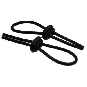
Eine Packung wiederverwendbarer selbstklebender 'Sticky Pads'-Elektroden.
1 PP3-Batterie für die Power Unit.
Eine große Auswahl an Elektroden und anderem Zubehör ist erhältlich. Für weitere Informationen besuchen Sie unsere Website und unsere Online-Shops
Wenn das E-Stim Systems Remote System über einen längeren Zeitraum nicht benutzt wird, entfernen Sie immer die Batterie, um Schäden durch auslaufende Batterien zu vermeiden. Der Schlüsselanhänger wird mit einer qualitativ hochwertigen Batterie geliefert, die nicht auslaufen sollte, aber es wird dennoch empfohlen, sie zu entfernen, wenn die Geräte über einen längeren Zeitraum nicht benutzt werden. Halten Sie die Batterien von Kindern fern und verschlucken Sie sie nicht!!!
Reinigung
Verwenden Sie KEINE Lösungsmittel zur Reinigung des Schlüsselbundes oder der Power Unit. Ein sanftes Abwischen mit einem weichen Tuch sollte ausreichen. Es ist nicht möglich, beide Einheiten zu sterilisieren.
Gürtelclip
Das E-Stim Systems Remote Power Unit ist mit einem Gürtelclip ausgestattet. Dieser Clip ist für die Befestigung an einem Gürtel oder Gurt vorgesehen und sollte nicht überdehnt werden.
Spezifikationen
Empfänger
Kanäle/ Ausgänge
Dynamischer Antrieb, einkanalig, über eine 3,5mm Mono-Buchse nach Industriestandard.
Display
9 Leuchtdioden mit hoher Helligkeit zur Anzeige von Senderaktivität, Ausgangsaktivität und Status.
Betriebsmodi
27 Stufen in 10 Modi, darunter 2 Audiomodi und 2 bewegungsempfindliche Modi
Hochspannungsstrombegrenzter, gepulster Wechselstrom mit dynamischen Ausgangswellenformen.
Netzteil
Standard 9 Volt Alkaline (PP3)
Batterie Lebensdauer
Abhängig von der Belastung und den Eingaben, aber schätzungsweise ca. 8 Stunden bei Dauerbetrieb.
Abmessungen (ca.)
112mm x 65mm x 41mm
Gewicht (mit Batterie)
146g
Schlüsselanhänger-Sender
Typ
Schlüsselanhänger als Sender mit 4 Tasten und automatischer Abschaltung
Frequenz
KEELOQ kodiert AM 433.92Mhz
Reichweite
Bis zu 100M unter optimalen Bedingungen
Abmessungen
32,7mmm x 59mm x8mm
Gewicht (mit Batterie)
17g
Stromversorgung
3V (CR2032)
Schutzmaßnahmen
IP68
Probleme?
In dem unwahrscheinlichen Fall, dass Sie Probleme mit dem Betrieb Ihres E-Stim Systems Remote Systems oder einem der mitgelieferten Zubehörteile haben, wenden Sie sich bitte an Ihren ursprünglichen Lieferanten oder senden Sie eine E-Mail an info@e-stim.co.uk Geben Sie dabei die Seriennummer und das Problem an, das Sie festgestellt haben. Es gibt keine vom Benutzer zu wartenden Teile im Inneren und das Brechen von Siegeln führt zum Erlöschen der Garantie.
Lebenslange Garantie
Alle Geräte sind durch unsere lebenslange Garantie gegen Ausfälle aufgrund von Herstellungsfehlern während der gesamten Lebensdauer des Geräts bei normalem Gebrauch abgedeckt.
Die Garantie umfasst die Kosten für Teile und Arbeit, beinhaltet nicht den Versand und gilt nur für den Erstkäufer. Ein Kaufnachweis kann erforderlich sein.
Sicherheitswarnung
VERBINDEN SIE DIE E-STIM SYSTEM REMOTE POWER UNIT ODER IRGENDEIN ELEKTRISCHES GERÄT NICHT MIT EINER STELLE ÜBER DER HÜFTE (ÜBER DEN ARMEN ZÄHLT ALS ÜBER DER HÜFTE!), ABER BESONDERS NICHT ÜBER DEM HERZEN, DER BRUST, DEM HALS ODER DEM KOPF VERBINDEN. NICHT VERWENDEN, WENN SIE EINEN HERZSCHRITTMACHER TRAGEN ODER SCHWANGER SIND. DENKEN SIE DARAN, DASS SIE DIESES GERÄT AUF IHR EIGENES RISIKO BENUTZEN. SIE MÜSSEN DIE BEDIENUNGSANLEITUNG UND ALLE ANDEREN ANWEISUNGEN LESEN UND VERSTEHEN, BEVOR SIE DEN BETRIEB VERSUCHEN.
Konformitätszertifikat
Hinweis zur US-Regulierung für drahtlose Kommunikation
Dieses Gerät entspricht den Bestimmungen von Teil 15 der FCC-Bestimmungen. Der Betrieb unterliegt den folgenden zwei Bedingungen: (1) Dieses Gerät darf keine schädlichen Interferenzen verursachen und (2) dieses Gerät muss alle empfangenen Interferenzen akzeptieren, einschließlich Interferenzen, die einen unerwünschten Betrieb verursachen können.
Die FCC verlangt, dass der Benutzer darauf hingewiesen wird, dass jegliche Änderungen oder Modifikationen am Gerät, die nicht ausdrücklich von E-Stim Systems Ltd. genehmigt wurden, die Berechtigung des Benutzers zum Betrieb des Geräts aufheben können.
Hinweis für die Europäische Union
Produkte, die die CE-Kennzeichnung tragen, entsprechen der R&TTE Richtlinie (2014/53/EU), der EMV-Richtlinie (2014/30/EU) und der Niederspannungsrichtlinie (2014/35/EU) der Kommission der Europäischen Gemeinschaft.
Die Einhaltung dieser Richtlinien setzt die Konformität mit den folgenden europäischen Normen voraus (in Klammern sind die entsprechenden internationalen Normen und Vorschriften angegeben)
EN 55022 (CISPR 22) - Elektromagnetische Interferenz,
EN 55024 (IEC61000-4-2,3,4,5,6,8,11) - Elektromagnetische Störfestigkeit, und,
EN 60950 (IEC 60950) - Produktsicherheit.
Europa: Die Sender verwenden ECM-konforme Funksendemodule und entsprechen den Normen ETSI330-220 und ETSI300-683.
Dieses Gerät darf in allen Ländern der Europäischen Union verwendet werden.
Congratulations on purchasing a new E-Stim Systems Remote System. Given sufficient care your Remote System should give you many years of erotic electro stimulated pleasure. Before starting always read the instructions and ensure you are completely familiar with all of the controls and the safety warnings prior to use.
10 adjustable control modes, with 27 output levels, all controlled from a custom 4 button digital Keyfob.
Build in Dual Mode Audio driven trigger system with adjustable sensitivity and response.
Adjustable Motion Sensor
Uniquely digitally encoded Keyfob transmitters. Power units will not respond to other radio sources.
Up to 100M range
Learn mode allows multiple Keyfobs to be used in combination as well as multiple Power Units.
New Dynamic Drive Single channel output allows the use of unipolar and bipolar electrodes.
Current limited AC output to ensure safety and avoid the possibility of electrode polarisation.
SAFETY WARNING
DO NOT CONNECT THE E-STIM SYSTEM REMOTE POWER UNIT OR ANY ELECTRICAL DEVICE TO ANY LOCATION ABOVE THE WAIST (ACROSS THE ARMS COUNTS AS ABOVE THE WAIST!), BUT ESPECIALLY DO NOT CONNECT ACROSS THE HEART, CHEST, NECK OR HEAD. DO NOT USE IF FITTED WITH A PACEMAKER OR ARE PREGNANT. REMEMBER YOU USE THIS DEVICE AT YOUR OWN RISK. YOU MUST READ AND UNDERSTAND THE USER MANUAL AND ALL OTHER INSTRUCTIONS BEFORE ATTEMPTING OPERATION.
What's in the Pack?
Contents
The new E-Stim Systems Remote system consists of two units, a small hand held 'key fob' style transmitter and the Power Unit radio receiver. The Power Unit is connected to an electrode that is attached or inserted into your subject, whilst the Keyfob transmitter provides the control from a distance of up to 50M (~150ft). The Pack also consists of a set of sticky pads, a 2mm/TENS connection cable, and a battery for the Power Unit (the battery for the Keyfob (CR2032) is already fitted). A quick guide is now also provided to give you a quick insight into the controls useful for when you don't have access to this online manual.
The distance over which the Power Unit will respond to the Keyfob transmitter is highly dependent on the environment, battery levels, and a number of other factors.
The remote allows 27 levels of output in 10 different modes. All controls including level and mode selection are via a simple up/down/select system on the Keyfob.
The system also allows the use of multiple Keyfobs and receivers. As each Keyfob generates a unique code, it is possible to 'teach' a Power Unit to respond to a number of Keyfobs, and conversely, it is also possible to have a number of receivers responding to a single Keyfob .
Before Use
Before you can use your E-Stim Systems Power Unit you need to ensure that the Power Unit has recognised and is responding to the Keyfob . If you insert a battery into the receiver, switch the unit on with no electrodes connected and press the red button on the Keyfob , two LED's should light on the receiver. The RX LED should flicker and the output LED should illuminate for the period of time the red button on the Keyfob is depressed.
If the activity LED flickers but the output LED does not illuminate, this indicates that the Power Unit has not recognised the Keyfob . In this case you need to follow the LEARN procedure.
Startup
On startup the Power Unit will perform a self test and display the battery level before selecting the last mode used. The remote system now remembers the previous mode the unit was in last time it was switched off, as well as the adjustment level. To reset the unit to Factory setting, follow the Factory reset procedure. The output level will always be set to zero when the Power Unit is switched on.
Using the Remote System
Step 1 Fit the batteries The Keyfob is supplied with the battery fitted.
Step 2 Ensure the Keyfob is linked to the Power Unit (Learn Mode)
Familiarise yourself with the controls on the Keyfob.
Depending on the mode generally the UP button increases the output level, the DOWN button decreases the output level, and the FIRE button activates or overrides the output, depending on the current mode selected. The ADJUST Button provides adjustment in each mode. In Training Mode, the Down button gives 25% output, the Adjust button gives 50% output, the UP Button gives 75% out and and the Fire button gives 100% output.
Pressing both the DOWN and ADJUST buttons together will switch the unit into mode select. See Mode Control.
Holding a level button will increase or decrease the output in larger steps. If you hold a button down for more than around 30 seconds the Keyfob will automatically shut down to save batteries (This is designed to stop inadvertent activation of the Keyfob in a pocket). If this occurs, simply release the button and press again.
If the LED on the Keyfob appears dim, and range is reduced then the Keyfob battery may need to be replaced.
Connecting an electrode
Ensure the Power Unit is turned off, and connect a suitable electrode via the output socket. Connect an electrode to a suitable section of the body. (DO NOT CONNECT THE Power Unit UNIT OR ANY ELECTRICAL DEVICE TO ANY LOCATION ABOVE THE WAIST (ACROSS THE ARMS COUNTS AS ABOVE THE WAIST!), BUT ESPECIALLY DO NOT CONNECT ACROSS THE HEART, CHEST, NECK OR HEAD. DO NOT USE IF FITTED WITH A PACEMAKER OR ARE PREGNANT. REMEMBER YOU USE THIS DEVICE AT YOUR OWN RISK.
Turn the Power Unit on, the output LED should flash 4 times and automatically select the previous mode 1 and then press the red button. Your subject may feel a slight tingling sensation from the electrode site. If not increase the level and try again. Adjust the output level as required.
If you or your subject experiences any pain or discomfort then stop using immediately. If we recommend the use of conductive lubrication as any E-Stim device is potentially capable of causing burning when used on sensitive and or small contact areas at high output levels.
Always ensure all connections are secure and free from corrosion.
DO NOT SHORT CIRCUIT the output. DO NOT attempt to open the Power Unit unit. High voltages are present even when the unit is switched off and there are no user serviceable parts inside. Opening the Power Unit will invalidate your guarantee.
Fitting Batteries
Both the Keyfob and the Power Unit require batteries to operate. The Keyfob is supplied fitted with a battery, whilst the Power Unit unit needs to have a battery fitted (not supplied).
Fitting a battery (Power Unit)
Ensure the unit is switched off, and any electrodes connection cables are disconnected.
Turning the unit over press gently down on the center of the battery cover and slide the cover downwards.
Remove the old battery (if fitted) and replace with a fresh alkaline PP3. The battery connector is polarized so it should not be possible to connect the battery incorrectly, but ensure the polarity is correct before attempting connection.
Place the battery into the unit and replace the battery compartment cover. The cover will slide and then should then click into position.
Turn the unit over. The unit is now ready for operation.
Please note we do NOT recommend the use of Zinc Carbon or standard re-chargeable batteries in the E-Stim Systems Remote Power Unit. NiMh re-chargeable batteries, with a terminal voltage of 8.4V or above may be used with a possible reduction in output power.
In the event the Power Unit is not being used for a period of time, remove the battery to avoid any possible damage due to batter leakage.
Fitting a battery (Keyfob)
Before changing the battery ensure that the Power Unit unit is turned off and disconnected from any electrodes. The Keyfob is supplied with a battery (CR2032) installed.
In order to replace the battery, use a small 'Phillips' or cross head type screwdriver to unscrew the two screws on the back of the Keyfob , being careful not to loose them.
Open the case and gently remove the battery. Insert the new battery, noting the polarity marked by a '+' on the board and the battery and close the case.
Replace the screws and screw the Keyfob back together.
Check that the battery has been correctly inserted by pressing a button on the Keyfob (ensuring that any Power Unit in range is turned off). The yellow LED on the Keyfob should flash for the duration of the press. In the event that it does not, check you have replaced the battery correctly.
Level Control
in general most modes use the up and down buttons to control the level. When the level is selected the level is displayed on the status bar, unless you are in Discreet Mode. As we need to display 28 levels (we don't count zero as an actual level but it is), and need to show 4 different levels between each led. As the level increases the status display will show a growing bar graph with each successive LED flashing slowly, flashing faster, flashing even faster then switching to a solid glow. Then the next LED in the display will continue the cycle. As an example:
Slow Flash
Level 1
Medium Flash
Level 2
Fast Flash
Level 3
Solid
Level 4
Pressing and holding the UP or DOWN button will result in the level jumping to the next 4th step i.e. 4 8 12 16 20 etc etc. Pressing and holding the DOWN button continuously will eventually result in the zero level being reached, when a quick LED wipe will display.
Most modes have some form of adjustment. Repeatedly pressing and releasing the ADJUST button will cycle through the individual adjustment for the current mode. The effect of the actual adjustment will depend on the mode. The adjust dot display will show for a couple of seconds after the adjust button has been released.
If Discreet mode has been selected, the adjust dot display will not show.
Mode Control
Mode Selection
Pressing both DOWN and ADJUST buttons on the keyfob together AT THE SAME TIME will switch the Power Unit into mode selection mode, indicated by a two solid LEDs showing on the status bar on the receiver. The position of the LEDs will indicate the current mode, the left on the far left indicates modes on the top row can be selected, the LED on the far right indicates modes on the bottom row can be selected. A mode is not selected until the ADJUST button has been pressed.
Pressing either the UP button or DOWN buttons will cycle up and down through the modes. Pressing the ADJUST button will activate the currently selected mode. The mode is not active until it has been selected. The mode is indicated by the left or right LED showing if you are on the top or bottom of the list of modes, and then a second LED showing the mode. As an example this is FIRE mode.
And this is Flo Mode
When the mode has been selected the status display will flash 3 times and then the output level is automatically set to zero. and the Adjust value set to 1. The current mode is remembered when the Power Unit is switched off.
The modes are as follows.
Fire Mode
The classic remote control mode. The UP and DOWN buttons control the output level (Zero to 27), whilst pressing the FIRE button will activate the output at the selected level as well as showing the output level on the Status display (unless you are in Discreet mode). The output will be active for the time the fire button is pressed, however the Keyfob will timeout after around 25 - 30 seconds cutting the output. The output LED will only be illuminated when the output is active. The Adjust button changes the feel of the output over 7 different values.
Flo Mode
A continuous output mode. The UP and DOWN buttons control the output level (Zero to 27), whilst pressing the FIRE button will give a boosted output 4 levels higher than the current setting (assuming there are any levels left and assuming your level is not set to zero. If the Power Unit is set to Level Zero then the output will not operate in boost mode when the fire button is pressed. ) Adjust cycles through several different ‘feelings’. Helix. In operation the Output LED will be on continuously. The Level output is not shown in Discreet Mode.
Pulse Mode
A pulsed output mode. The UP and DOWN buttons control the output level (Zero to 27), whist pressing the ADJUST button will cycle through 7 different pulse speeds from slow to fast. The FIRE button will override the output to give a continuous output. Level output is not shown in Discreet Mode.
Training Mode
The Classic 'Training Mode' No need to worry about what level the output is when you press the first button, as the outputs are preselected. DOWN Button gives 25% output, ADJUST 50% UP 75% and FIRE 100%. Assuming you are not using discreet mode the status display bar will indicate the output level.
25%
50%
75%
100%
Teese
A continuous output mode with a rising feel, indicated by a moving LED on the status bar. Once a cycle is complete it starts from zero. UP and DOWN buttons control the level, and the FIRE button boosts the output 4 steps above the current output. The boost does not work if the output level is set to zero. The ADJUST button control the speed of the cycle with 7 different speeds available.
Torment
A continuous output mode with a rising and dropping feel, indicated by a moving LED on the status bar. Once a cycle is complete the cycle reverses. UP and DOWN buttons control the level, and the FIRE button boosts the output 4 steps above the current output. The boost does not work if the output level is set to zero. The ADJUST button control the speed of the cycle with 7 different speeds available.
Audio Modes
Audio modes use sound to activate the output. The nature of the sound, the distance the sound source is from the Power unit , the level and the settings of the power unit in temrs of mode and adjustment selected all will effect how the sound is felt as an E-Stim sensation.
Audio Low Mode
Uses the inbuilt microphone to trigger the output. The ADJUST button controls the response, from highly sensitive to less sensitive. The Level controls UP and DOWN provide a multiple of the input so a maximum input with the level set to 27 (Full) will give the maximum output, where the same input with the level set to 14 will give half that output. The FIRE button artificially overrides the input giving the equivalent of a 100% input. Audio Low mode is not as sensitive as the Audio High Mode and is better used in more noisy environments.
Audio High Mode
Uses the inbuilt microphone to trigger the output with a higher sensitivity than the Audio Input Low mode. UP and DOWN button control the level out the output, ADJUST controls the sensitivity and FIRE overrides the output.There are 7 levels of adjustment via the ADJUST control. The display is different to the Audio Low mode as it is a bargraph increasing from the left side giving a more sensitive display. The FIRE button artificially overrides the input giving the equivalent of a 100% input.
Motion Low Mode
Motion Sensitive mode. The UP and DOWN buttons control the output level (1-27), whilst pressing the FIRE button will override the motion trigger and activate the output. If the Power Unit is moved excessively then the output will trigger. WARNING it is very sensitive!!. In operation the output LED will flicker when the output is active.
The motion sensor is very sensitive. In use the internal microprocessor counts the number of times the sensor is triggered and when this reaches a set level the output will fire. As the level builds up the bargraph will increase. Once all 7 bars are illuminated the Output will trigger. The trigger point is adjustable depending on the adjust setting. should no movement occur then the bargraph display will gradually decay over time. Pressing the FIRE button will override the output and ‘zap’ the subject, possibly causing even more movement!!
The motion sensor is active in any orientation.
Receiver
The Power Unit has two simple controls and 3 Displays.
Power Unit Displays
LED
Use
Output
Indicates output activity and mode. In mode select mode, the number of flashes indicates the mode. On startup the Output LED will flash 3 times in quick succession.
Status Bar
Used to indicate the battery level, current output level, mode and adjustment
RX
Indicates Radio activity. Will also indicate when the Power Unit is in LEARN mode. Note that the RX LED will indicate activity when any compatible Keyfob is used within range, even if that Keyfob has not been learnt by the receiver.
Learn mode allows the user to select which Keyfobs the Power Unit will respond to. It is possible to 'teach' a Power Unit to respond to up to 50 separate Keyfobs, and it is also possible to teach more than one Power Unit to respond to the same Keyfob .
The Power Unit is initially supplied with one Keyfob that is linked with the Power Unit during testing, and should operate 'out of the box'. Learn mode is generally only needed if you have purchased replacement or additional Keyfobs or receivers
The learn button is inside the battery compartment. Open the Battery Compartment, remove the battery, but do not disconnect it, and you should find the learn button inside. The learn button will only operate when the Power Unit has a battery connected and is powered on, so DO NOT DISCONNECT THE BATTERY.
Clearing the Power Unit memory
Clearing all Keyfobs. This will remove all Keyfob s from the Power Unit memory.
Remove the battery from the battery compartment but ensure that it is still connected. Turn the power unit on. Hold down the learn button for at least 10 seconds. The RX LED will illuminate. Release the learn button. The RX LED should now blink around 10 times and then stop. The memory has now been cleared.
Teaching the Power Unit to recognise a remote.
Remove the battery from the battery compartment but ensure that it is still connected. Turn the power unit on.
Press the learn button once. The RX LED should illuminate. Press a button on the Keyfob you wish to use with the receiver. The RX LED should now go out. press the button again. The RX LED should now blink several times. The Power Unit has now 'learnt' the Keyfob and will now respond to the Keyfob. Additional Keyfobs can also be added so one Power Unit will respond to more than one Keyfob. It is also possible to add a single Keyfob to more than one Power Unit giving even more possibilities.
Outputs
Connection to electrodes is via a single 3.5mm mono jack socket on the top of the receiver. Ensure the unit is switched off before inserting or removing the connection jacks to eliminate the possibility of either inadvertent electric shocks or short circuits occurring. We recommend the use of E-Stim Systems 3.5mm Right Angled connectors as this will reduce the possibility of damage occuring to the output socket.
Adapters are available for 2mm and 4mm connectors.
Extra Controls
Factory Reset
Both the current mode and the adjustment setting for that mode are remembered when the receiver is switched off. To reset the Power Unit back to a factory default of FIRE mode and adjustment setting of 1, Press and hold the DOWN button when switching the unit on. The unit will then show three fast dot 'zips' from right to left and then reset the mode to FIRE and the adjustment to 1. Output levels are always set to zero when the Power Unit is first switched on.\
Discreet Mode
Discreet mode switches the status bar off for discreet play. Simply press and hold the ADJUST button on the keyfob when switching the Power Unit on. The Status display will then show two fast dot 'zips' from low to high' and then the battery status before switching the status display off. From then on the status display will only illuminate for mode changes. To switch discreet mode off simply switch the Power Unit off and then on again. Discreet mode is not remembered when the unit is switched off.
Accessories
The E-Stim Systems Remote System Pack is supplied in a custom fitted carry case with:-
The Power unit (Receiver).
A Keyfob (Fitted with a CR2032 Battery)
A 1.5M connection cable fitted with a 3.5mm right angled jack plug on one end (for connection to the Power Unit unit) and two colour coded 2mm plugs on the other, to connect to E-Stim Electrodes fitted with 2mm or TENS style sockets.
A Quick Guide Card.
A pack of re-usable self adhesive 'Sticky Pads'.
1 PP3 Battery for the Power Unit.
A wide range of electrodes and other accessories are available. For more information visit our website and online stores at
In the event that the E-Stim Systems Remote System is not going to be used for a period of time always remove the battery to avoid any possibility of damage being caused by battery leakage. The Keyfob is supplied with a high quality battery, that should not leak, but it is still recommended that they are removed if the units are not being used for a long period. Keep the batteries away from Children and do not swallow them!!
Cleaning
DO NOT use solvents to clean either the Keyfob or the Power Unit. A gentle wipe with a soft cloth should be sufficient. It is not possible to sterilise either unit.
Belt Clip
The E-Stim Systems Remote Power Unit is fitted with a belt clip. This clip is designed to clip on a belt or harness and should not be over extended.
Specifications
Receiver
Channels/ Outputs
Dynamic Drive, Single Channel, via an industry standard mono 3.5mm socket.
Display
9 High Brightness Light Emitting Diodes indicating Transmitter Activity, Output Activity and Status.
Operating Modes
27 Levels in 10 modes, including 2 Audio Modes and 2 Motion Sensitive modes
Controls
Slide switch for Power On/Off.
Push button for LEARN mode (insider battery compartment)
Non Mercury Vibration Sensor (Internal)
Output Waveform
High Voltage current limited, pulsed AC with Dynamic width output waveforms.
Power Supply
Standard 9 Volt Alkaline (PP3)
Battery Life
Variable dependent on load and input, but estimated at around 8 hours with continuous use.
Dimensions (approx.)
112mm x 65mm x 41mm
Weight (with battery)
146g
Keyfob Transmitter
Type
4 Button custom Keyfob transmitter with Auto Power Off
Frequency
KEELOQ Encoded AM 433.92Mhz
Range
Up to 100M under optimum conditions
Dimensions
32.7mmm x 59mm x8mm
Weight (with Battery)
17g
Power Supply
3V (CR2032)
Protection
IP68
Problems?
In the unlikely event you have problems with the operation of your E-Stim Systems Remote System, or any of the supplied accessories, then contact your original supplier or email info@e-stim.co.uk quoting the serial number and the problem you have encountered. There are no user serviceable parts inside and the breaking of any seals with invalidate your guarantee.
Lifetime Guarantee
All units are covered by our Lifetime Guarantee, against failure due to manufacturing defects for the lifetime of the unit subject to normal use.
The Guarantee includes the cost of parts and labour, does not include shipping and only applies to the original purchaser. Proof of purchase may be required.
SAFETY WARNING
DO NOT CONNECT THE E-STIM SYSTEM REMOTE POWER UNIT OR ANY ELECTRICAL DEVICE TO ANY LOCATION ABOVE THE WAIST (ACROSS THE ARMS COUNTS AS ABOVE THE WAIST!), BUT ESPECIALLY DO NOT CONNECT ACROSS THE HEART, CHEST, NECK OR HEAD. DO NOT USE IF FITTED WITH A PACEMAKER OR ARE PREGNANT. REMEMBER YOU USE THIS DEVICE AT YOUR OWN RISK. YOU MUST READ AND UNDERSTAND THE USER MANUAL AND ALL OTHER INSTRUCTIONS BEFORE ATTEMPTING OPERATION.
Certificate of Conformity
US Regulatory Wireless Notice
This device compiles with Part 15 of the FCC Rules. Operation is subject to the following two conditions: (1) this device may not cause harmful interference, and (2) this device must accept any interference received, including interference that may cause undesired operation.
The FCC requires the user to be notified that any changes or modifications made to the device that are not expressly approved by E-Stim Systems Ltd may void the users authority to operate the equipment.
European Union Notice
Products bearing the CE marking comply with the R&TTE Directive (2014/53/EU), EMC Directive (2014/30/EU), and the Low voltage Directive (2014/35/EU) issued by the Commission of the European Community.
Compliance with these directives implies conformity to the following European norms (in parentheses are the equivalent international standards and regulations.)
EN 55022 (CISPR 22) – Electromagnetic Interference,
EN 55024 (IEC61000-4-2,3,4,5,6,8,11) – Electromagnetic Immunity, and,
EN 60950 (IEC 60950) – Product Safety.
Europe: The transmitters use ECM compliant radio transmitter modules and comply with ETSI330-220 and ETSI300-683.
This device may be used in all European Union Countries.
Comment nous utilisons les cookies et autres données
En sélectionnant Accepter tout", vous nous donnez la permission d'utiliser les services suivants sur notre site web : YouTube, Vimeo, ReCaptcha, Brevo, OSS Lieferland Geo-Ip Dienst, Klaviyo, Tawk Livechat, Tawk Livechat, Google Tag Manager, Google Analytics, Google Ads, Google Tag Manager, dash.bar. Vous pouvez modifier les paramètres à tout moment (icône d'empreinte digitale dans le coin inférieur gauche). Pour plus de détails, veuillez consulter Configuration individuelle et notre Avis de confidentialité."
Paramètres de confidentialité des données
Les paramètres que vous spécifiez ici sont enregistrés dans le stockage local" de votre appareil. Les paramètres seront mémorisés pour la prochaine visite de notre boutique en ligne. Vous pouvez modifier ces paramètres à tout moment (icône d'empreinte digitale dans le coin inférieur gauche).
Pour plus d'informations sur la durée de vie des cookies et les cookies essentiels requis, veuillez consulter la notice de confidentialité."
Pour débloquer le contenu de YouTube sur ce site, votre accord est nécessaire pour le partage des données et le stockage des cookies tiers du fournisseur YouTube (Google). Cela nous permet daméliorer notre offre ainsi que lexpérience utilisateur et de la rendre plus intéressante pour vous. Sans votre accord, aucune donnée nest transmise à YouTube, mais les fonctions de YouTube ne peuvent alors pas être utilisées sur ce site.
Pour débloquer le contenu de Vimeo sur ce site, votre accord est nécessaire pour le partage des données et le stockage des cookies tiers du fournisseur Vimeo. Cela nous permet daméliorer notre offre ainsi que lexpérience utilisateur et de la rendre plus intéressante pour vous. Sans votre accord, aucune donnée nest transmise à Vimeo, mais les fonctions de Vimeo ne peuvent alors pas être utilisées sur ce site.
Um Formulare auf dieser Seite absenden zu können, ist Ihre Zustimmung zur Datenweitergabe und Speicherung von Drittanbieter-Cookies des Anbieters Google erforderlich.
Durch Ihre Zustimmung wird reCAPTCHA, ein Dienst von Google zur Vermeidung von Formular-SPAM, eingebettet.
Dieser Dienst erlaubt uns die sichere Bereitstellung von Online-Formularen für unsere Kunden und schließt gleichzeitig SPAM-Bots aus, welche ansonsten unsere Services beeinträchtigen könnten.
Sie werden nach Ihrer Zustimmung unter Umständen dazu aufgefordert, eine Sicherheitsabfrage zu beantworten, um das Formular absenden zu können.
Stimmen Sie nicht zu, ist eine Nutzung dieses Formulars leider nicht möglich. Nehmen Sie bitte über einen alternativen Weg zu uns Kontakt auf.
Um Daten an Brevo zu übermitteln, ist Ihre Zustimmung zur Datenweitergabe und Speicherung von Drittanbieter-Cookies des Anbieters Brevo erforderlich. Dies erlaubt uns, unser Angebot sowie das Nutzererlebnis für Sie zu verbessern und interessanter auszugestalten.
Der Geo-Ip Dienst dient lediglich der Bestimmung des Landes aus dem der Benutzer diese Seite besucht, um automatisch länderspezifische Steuersätze und Preise anzuzeigen zu können.
Description:
Länderbestimmung für länderspezifische Steuersätze
This is a web analysis service. It allows the user to measure advertising return on investment (ROI) and track user behavior. Data collected: anonymized IP address, date and time of visit, usage data, click path, app updates, browser information, device information, JavaScript support, pages visited, referrer URL, location information, purchase activity, widget interactions.
This is an advertising service. This service can be used to display personalized or non-personalized advertising to users. With Google Ads Conversion Tracking, we can measure our advertising success in the Google advertising network. We place advertisements in the Google advertising network so that our offers can be found more easily. We try to optimize our advertising as much as possible. Also to keep advertising costs as low as possible. This is reflected in our prices.
This is a tag management system. The Google Tag Manager allows tags to be integrated centrally via a user interface. Tags are small sections of code that can track activities. Script codes from other tools are integrated via the Google Tag Manager. The Tag Manager makes it possible to control when a specific tag is triggered.
Souhaitez-vous voir ces contenus ? Activez les contenus souhaités pour une seule session ou autorisez le site web à se souvenir de ces paramètres. Une fois que vous avez donné votre consentement, les données de tiers peuvent être chargées. Pour ce faire, des cookies tiers peuvent être stockés sur votre appareil. Vous pouvez modifier ces paramètres à tout moment (icône d'empreinte digitale dans le coin inférieur gauche). Pour plus de détails, veuillez consulter la notice de confidentialité."


 Das neue E-Stim Remote System besteht aus zwei Einheiten, einem kleinen Handsender im Stil eines Schlüsselanhängers und dem Funkempfänger, die Power Unit. Die Power Unit wird an eine Elektrode angeschlossen, die an der Person angebracht oder in sie eingeführt wird, während der Schlüsselanhänger-Sender die Steuerung aus einer Entfernung von bis zu 50 m ermöglicht. Das Paket enthält außerdem einen Satz Klebepads, ein 2-mm-TENS-Verbindungskabel und eine Batterie für die Power Unit (die Batterie für den Schlüsselanhänger (CR2032) ist bereits eingebaut). Außerdem wird eine Kurzanleitung mitgeliefert, die Ihnen einen schnellen Einblick in die Bedienelemente gibt, wenn Sie keinen Zugang zu dieser Online-Anleitung haben.